
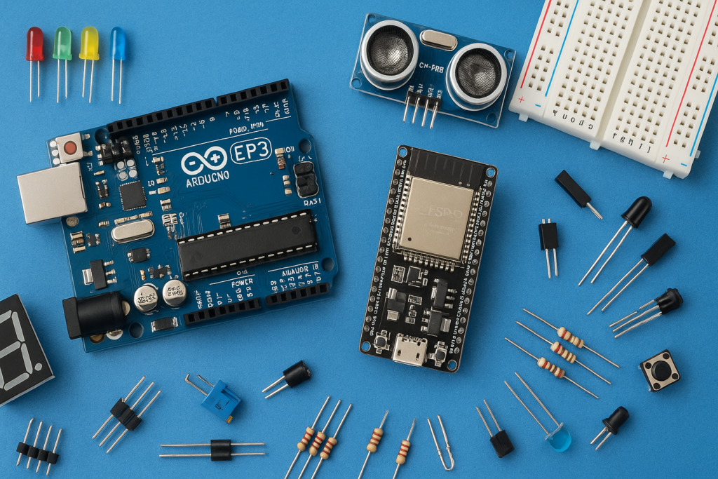
Want to make two LEDs blink alternately without using an Arduino,
555 timer IC or microcontroller?
This simple circuit uses two BC547 transistors,
resistors and capacitors to create a continuous blinking effect.
The circuit is called a
transistor astable multivibrator.
What is an Astable Multivibrator?
An astable multivibrator is an electronic circuit that continuously
switches between two states.
In this project, when one transistor turns ON, the other transistor
turns OFF. After a short period of time, they exchange their states.
This process repeats continuously.
Because the two LEDs are connected to the collectors of the
transistors, the LEDs blink alternately.
Components Required
| Component | Quantity |
|---|---|
| BC548 NPN Transistor | 2 |
| 47 kΩ Resistor | 2 |
| 330 Ω Resistor | 2 |
| 100µF Capacitor | 2 |
| LED | 2 |
| 9V Battery / DC Supply | 1 |
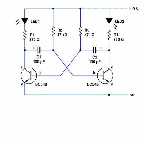
Circuit:
How Does the Circuit Work?
The two BC547 transistors are connected so that the output of one
transistor affects the base of the other transistor through a capacitor.
When transistor Q1 turns ON, transistor Q2 is driven OFF.
The capacitor then starts charging through the resistor connected
to the base of Q2.
After the capacitor charges sufficiently, Q2 turns ON and Q1 turns OFF.
The same process then happens in the opposite direction.
In simple words:
Q1 ON → LED1 changes state → Q2 OFF
Then after a short delay…
Q2 ON → LED2 changes state → Q1 OFF
Then the process repeats.
What Determines the Blinking Speed?
The blinking speed is mainly determined by the
base resistors and capacitors.
In a symmetrical circuit like this one, both timing resistors have
the same value and both timing capacitors have the same value.
The important relationship is the
RC time constant.
Frequency Formula
f ≈ 0.72 / (R × C)
Or, when R is in kΩ and C is in µF:
f ≈ 720 / (R × C)
Here:
- f = frequency in Hertz (Hz)
- R = base resistor in kΩ
- C = capacitor in µF
How Long Does Each LED Stay ON?
Frequency tells us how many complete cycles happen every second.
But if we want to know how long one LED stays ON, we use the
following formula:
LED ON time ≈ 0.693 × R × C
when R is in kΩ and C is in µF
The complete cycle time is approximately:
T ≈ 1.386 × R × C
Frequency = 1 / T
Example: 22 kΩ and 4.7 µF
Let’s calculate the blinking speed of the circuit using these values
R = 22 kΩ
C = 4.7 µF
Frequency:
f ≈ 720 / (22 × 4.7)
f ≈ 6.97 Hz
Therefore, the circuit completes approximately
6.97 blinking cycles every second.
Each LED remains ON for approximately:
LED ON time ≈ 0.693 × 22 × 4.7
≈ 0.0717 seconds
≈ 72 milliseconds
Try Your Own Resistor and Capacitor Values
Astable Multivibrator Calculator
Enter your resistor and capacitor values below.
You don’t need to convert kΩ or µF.
What does this mean?
What Happens If I Change the Resistor?
Increasing the resistor value increases the charging time of the
capacitor.
Therefore:
Larger resistor → slower blinking
Smaller resistor → faster blinking
What Happens If I Change the Capacitor?
Increasing the capacitor value also increases the charging time.
Larger capacitor → slower blinking
Smaller capacitor → faster blinking
Beginner Tip
If you want the LEDs to blink more slowly, try increasing the
capacitor value.
For example, replacing 4.7 µF with 47 µF will make the circuit
blink approximately ten times slower, assuming the resistor
remains unchanged.
Important Note
The formulas above are approximate. Real-world frequency can vary
slightly because transistor characteristics, capacitor tolerance,
resistor tolerance and supply conditions affect the actual timing.
For a beginner project, however, these formulas provide a very good
estimate of the blinking speed.
Conclusion
This BC547 astable multivibrator is a great beginner electronics
project because it demonstrates how transistors, resistors and
capacitors can work together to create an automatic oscillating
circuit.
No Arduino, microcontroller or timer IC is required.
The two transistors continuously switch each other ON and OFF,
producing the alternating LED blinking effect.
Leave a Reply